Overview
Designing a robotic arm is more than drawing parts: you also need to know it can move smoothly, carry its own weight and reach the point you ask for. This project follows the whole path, from a multi-link arm designed in SolidWorks to a physics-based simulation in MATLAB Simscape Multibody.
Two models are included. A simple two-joint arm is used to learn PID tuning, and a larger five-part arm with a gripper is driven by inverse kinematics.
What the project is about
A robotic arm has to do more than look right: its parts must move smoothly, carry their own weight and reach the point you ask for. This project follows that whole path. The arm is designed in SolidWorks, brought into MATLAB as a physics model, and then given the maths to move to a target position.
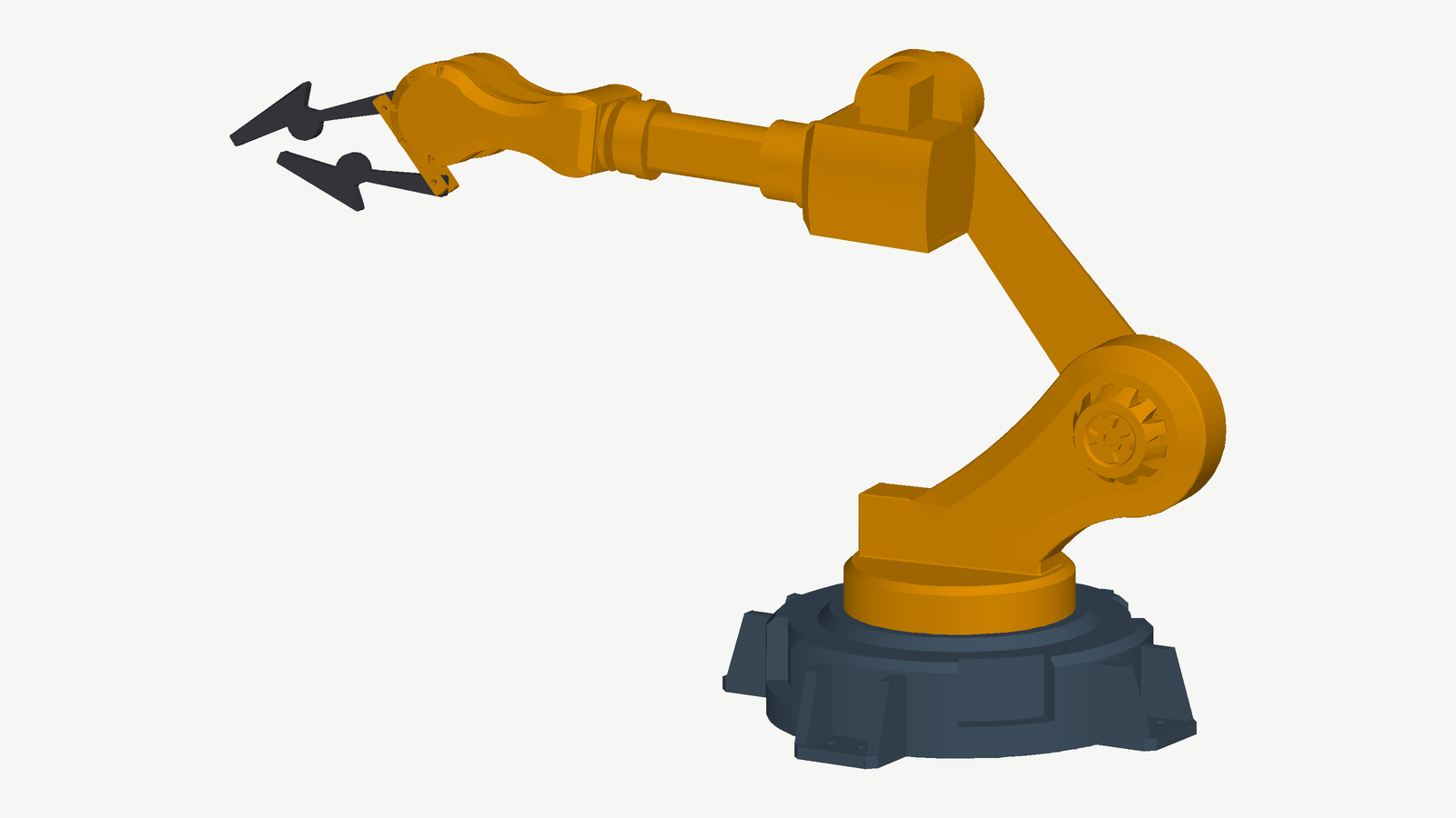
From CAD to a physical model
The arm was modelled as separate parts in SolidWorks and assembled. The assembly carries each part's mass, centre of mass and inertia, so when it is imported into Simscape Multibody the simulated arm feels gravity and joint loads like a real one. When the arm is stretched out, for example, the base joint really does need more torque to hold the pose.
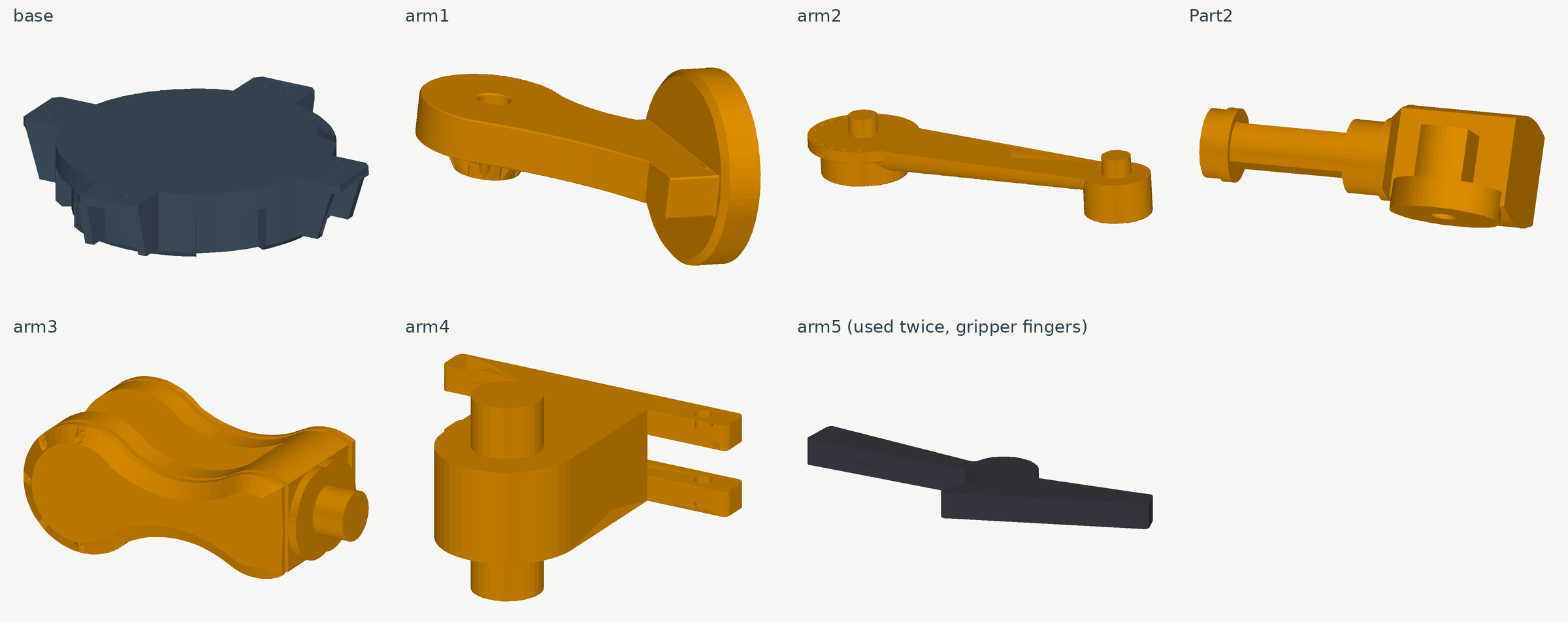
Two models
- 2-DOF tutorial arm: a simple two-joint arm used to study PID control, set a target point and watch how the gains change overshoot and settling.
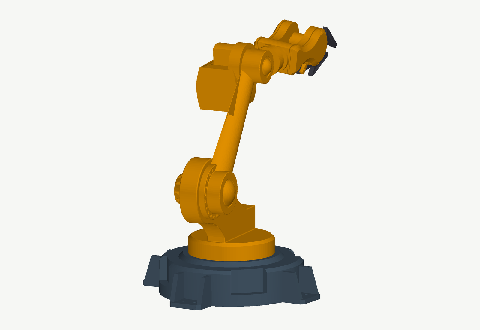
- Advanced arm: a larger arm with a base turntable, shoulder, elbow, wrist and a two-finger gripper, moved by inverse kinematics.
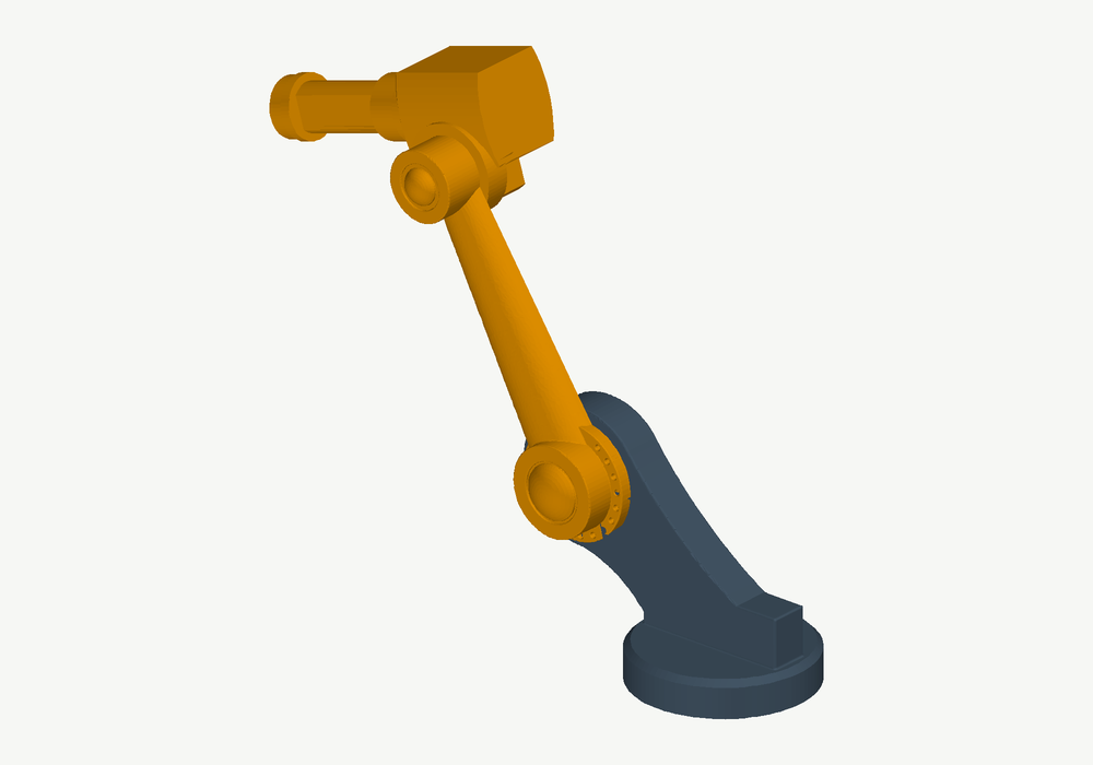
Telling the arm where to go
Instead of guessing each joint angle, you give the arm a point in space (X, Y, Z in millimetres) and the inverse kinematics script works out the angles. The base turns toward the target, and the shoulder and elbow are solved from the arm's link lengths with simple trigonometry. The wrist is then tilted to keep the gripper level. If the target is out of reach, the script warns and clamps it to the arm's maximum reach.
Making it simulate reliably
- Setup scripts load the model, fix the base to the table, lock the gripper joints and add the angle inputs, so the model is ready with one command.
- CAD imports often fail with a “degenerate mass” error when massless parts are joined directly. A tiny extra mass body between the joints (IntermediateMass) fixes it without changing the arm.

Where it stands
The arm moves in step jumps to each target rather than along a smooth trajectory, and the joint-angle offsets between the maths and the CAD model are marked for calibration in the scripts. Natural next steps are smooth trajectory planning, camera-based object detection and moving the control to ROS 2 for hardware tests.
CAD files, MATLAB scripts and setup instructions are in the project repository.